Description of the design
The crank drive can be designed with minimum space requirements. The ratio of width to stroke is approx. 1.5 to 1.
Due to the congruent contour of the segmented disks, the crankcase has a smooth, cube-shaped surface. It facilitates not only the assembly of exterior attachment parts, such as cylinder, valve controls, etc., but also sealing of the push rod in the housing and a possible installation of linear bearings.
The one-piece push rod is broadly supported by the two housing entries. This means the push rod can accept the transverse forces.
Cylinders for guiding the push rod are not necessary. This results in countless other applications, which also include the conversion of linear movements into rotary movements.
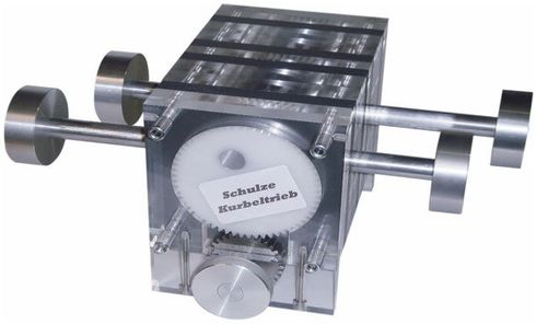
Design details of the eight disk basic model:
The rotating drive shaft is In the center of the x-axis. Also, in the center of the y-axis is the through piston rod, that only moves linearly. The surfaces vertical to the z-axis form the top and bottom sides of the housing.
Planes 1 and 8 are purely covers. In the base model they hold the bearings of the drive shaft.
Planes 2 and 7 form the guides for the plain bearing disks. These disks have holes for accepting the crankshaft journals. The center point of the holes lie exactly on the half-radius of the plain bearing disks.
On each crankshaft journal there is fastened a gear with exterior teeth, which turn as planetary gears in the inner-toothed sprockets of the square disks in Plane 3 and 6. The nominal diameter of the toothed gears is here exactly half as large as the nominal diameter of the square disks with inner-toothing.
In the center, between Plane 4 and 5, is the shaft journal of the crank shaft, that with precise alignment of the gears moves in a straight line on the crank journal. The axis distance between the crank journals and the shaft journals corresponds to half of the nominal diameter of the outer gears. The crank shaft is designed in two parts due to the installation of the push rod. Both parts are secured against turning. The eye of the push rod sits on the shaft journal, to which the linear movement of the shaft journal is transferred. The stroke of the push rod corresponds to the nominal diameter of the inside gears. The pushrod pushes through the square disks right and left and is guided by their walls.
Advantages
Almost double the working space with the same size; easy assembly, low maintenance and available spare parts; expandable with identical individual parts; adaptable; very versatile use. The crankshaft drive can easily be extended to two or three piston rods with the same parts in the version shown below. In doing so, the piston rods can be displaced by 180 degrees or 120 degrees by staggering the crankshaft pins in the plain bearing washers. Clamp free running due to uniform force introduction.
Almost double the working space with the same size; easy assembly, low maintenance and available spare parts; expandable with identical individual parts; adaptable; very versatile use. The crankshaft drive can easily be extended to two or three piston rods with the same parts in the version shown below. In doing so, the piston rods can be displaced by 180 degrees or 120 degrees by staggering the crankshaft pins in the plain bearing washers. Clamp free running due to uniform force introduction.